Rovix Motion Rovix Motion

What Is a High Torque Gear Motor and How Does It Work?

Time:2026-09-10 Author:Liam
0%

A High Torque Gear Motor combines an electric motor with a reduction gearbox. It delivers controlled rotational force at a slower output speed. This combination powers conveyors, lifting systems, automated gates, mixers, and industrial robots. The motor creates motion. The gearbox reshapes that motion into usable torque.

Mechanical-design authority Richard G. Budynas explains, “The function of gears is to transmit motion and power from one shaft to another.” That principle remains central to every High Torque Gear Motor. Smaller gears can drive larger gears, increasing output torque while reducing speed. The result feels practical: a compact motor turns a heavy conveyor roller without demanding extreme electrical input.

Real performance depends on more than the product label. Rated torque, starting torque, duty cycle, gear ratio, efficiency, backlash, and thermal limits all matter. A motor may lift a load briefly, yet overheat during continuous operation. Lubrication also matters. Dry gears create noise, friction, and premature wear.

The label can mislead.

A larger motor is not always better. Poor alignment, shock loading, or an undersized gearbox can shorten service life. Engineers should compare the load profile with manufacturer test data and application experience. This article examines what a High Torque Gear Motor is, how its internal stages work, and why correct sizing determines reliable performance. Some calculations look simple. Real machines are less forgiving.
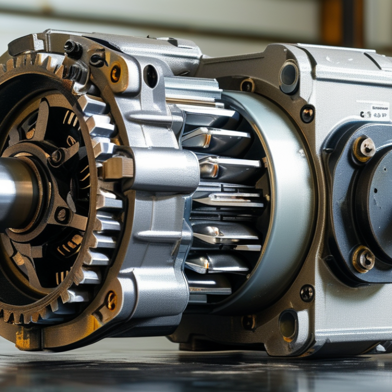
What Is a High Torque Gear Motor and How Does It Work?

High-Torque Gear Motor Definition: Torque, Speed, Power, and Typical Ratings

A high-torque gear motor combines an electric motor with a reduction gearbox. The motor spins quickly, while the gears reduce output speed and increase turning force. This makes the unit suitable for conveyors, lifting mechanisms, valves, and positioning systems. Output torque is usually measured in newton-metres (N·m), while speed is measured in revolutions per minute (rpm).

The basic relationship is simple: output torque roughly equals motor torque multiplied by the gear ratio and gearbox efficiency. A 20:1 gearbox can greatly increase torque, but output speed becomes about one-twentieth of motor speed. Power connects both values through the formula P = T × ω In practical terms, a motor cannot deliver maximum torque, maximum speed, and maximum efficiency at the same time. Something gives.

Typical ratings vary widely. Small units may provide 0.5–5 N·m, while industrial models can exceed 1,000 N·m. Rated torque describes continuous operation under stated conditions. Peak or stall torque may last only briefly.

I have seen selections fail because engineers compared peak figures instead of continuous ratings. The load’s starting torque, duty cycle, gearbox efficiency, and thermal limits also matter. A motor lifting a steady load behaves differently from one reversing every few seconds. Even a carefully calculated selection may need correction after testing, because friction, misalignment, and shock loads are easy to underestimate.

Core Components Explained: Motor, Gear Train, Bearings, Housing, and Output Shaft

What Is a High Torque Gear Motor and How Does It Work?

Core Components Explained: Motor, Gear Train, Bearings, Housing, and Output Shaft

A high torque gear motor combines an electric motor with a gear train. The motor creates rotational speed and mechanical power. The gears reduce speed while multiplying torque at the output shaft. This arrangement drives conveyors, lifting systems, valves, and automated machinery. The U.S. Department of Energy reports that motor-driven systems consume more than 69% of industrial electricity. Efficient mechanical transmission therefore matters.

The motor is the energy source, while the gear train controls speed and torque. Spur, helical, planetary, and worm gears offer different load and efficiency characteristics. Bearings support rotating shafts and limit friction. Small alignment errors can still create heat, noise, and premature wear. Engineers often overlook this detail. Proper lubrication and calculated bearing life are essential.

The housing holds the assembly in position and protects internal parts from dust, impact, and moisture. Its stiffness also helps maintain gear alignment under load. The output shaft transfers torque to the driven machine, so its diameter, keyway, and material need careful checking. A shaft that looks strong may still fail under repeated shock loads. The International Organization for Standardization’s ISO 281 bearing-life method supports more reliable service calculations, but field conditions remain difficult to predict. Temperature, vibration, duty cycle, and poor maintenance can change actual performance.

How Gear Reduction Multiplies Torque: T = 9550P/n and Ratio Calculations

A high torque gear motor combines an electric motor with a gearbox that reduces speed and increases usable torque. The key relationship is T = 9550P/n, where T is torque in newton-metres, P is power in kilowatts, and n is speed in revolutions per minute. This equation gives the motor’s approximate torque before gear reduction.

Consider a 1.5 kW motor running at 1,450 rpm. Its calculated torque is about 9.9 Nm. With a 20:1 gearbox, the output speed falls to roughly 72.5 rpm. The ideal output torque becomes 198 Nm, calculated as 9.9 × 20. Real systems deliver less. If gearbox efficiency is 90%, usable torque is near 178 Nm. Small losses matter.

The reduction ratio can be estimated from input and output speed: Ratio = input speed ÷ output speed. A conveyor requiring 70 rpm from a 1,400 rpm motor needs approximately a 20:1 reduction. However, torque demand should include starting loads, friction, shock, and duty cycles. A motor may lift a load smoothly but stall during startup. That detail is easy to miss. Heat, backlash, and lubrication also affect performance, so published torque values should not be treated as perfect field results. A modest safety margin is usually sensible, though excessive sizing wastes energy and increases cost. My calculation may look precise, but the machine rarely behaves so neatly.

Efficiency and Speed Trade-Offs: Typical 70–95% Gearbox Performance Range

What Is a High Torque Gear Motor and How Does It Work?

A high-torque gear motor combines an electric motor with a reduction gearbox. The motor spins quickly, while the gearbox lowers speed and multiplies torque. This design moves heavy loads through conveyors, lifts, mixers, and automated equipment. Torque rises as speed falls. Simple physics.

Efficiency is the difficult trade-off. Typical gearbox performance ranges from 70% to 95%, depending on gear type, load, lubrication, alignment, and operating speed. Spur and worm gearboxes often lose more energy through friction. Planetary and helical designs can achieve higher efficiency when correctly sized. The U.S. Department of Energy reports that motor-driven systems consume more than half of industrial electricity in many facilities. Even small gearbox losses can therefore increase heat, energy use, and maintenance costs. The 70–95% range is useful, but it is not a promise. Real equipment may perform worse under overload, poor lubrication, or repeated starts.

Tips: Check efficiency at the actual working load, not only the catalog rating. Measure input power, output torque, and temperature during normal operation. AGMA guidance emphasizes correct lubrication, alignment, and load selection for reliable gear performance. Engineers sometimes choose maximum torque and overlook speed stability. That mistake can create vibration, noise, and unnecessary power consumption. A slightly slower motor may deliver better control and longer service life.

High-Torque Gear Motor: Efficiency and Speed Trade-Offs

Typical gearbox efficiency ranges vary with gear architecture, reduction ratio, load, lubrication, and operating speed. Higher reduction ratios increase output torque but reduce output speed and may increase mechanical losses.

The ranges shown are representative engineering values for common high-torque gearbox configurations. Actual performance can differ according to duty cycle, temperature, alignment, and maintenance condition.

Sizing and Selection Criteria: Load Torque, Duty Cycle, Ratio, and IEC Ratings

A high torque gear motor combines an electric motor with a gearbox to produce controlled rotary force. The gearbox reduces speed and increases output torque. In practical sizing, begin with the driven load, not the motor nameplate. Measure running torque, starting torque, speed, and shaft inertia. Peak demand matters.

Calculate required torque with a realistic service factor. A conveyor carrying uneven boxes may need short bursts above its average load. Select a motor that handles those peaks without overheating. However, an oversized motor can waste energy and reduce control quality. I have seen many sizing errors caused by ignoring friction, belt tension, or acceleration time.

Duty cycle affects thermal performance. Continuous operation requires a motor and gearbox rated for sustained heat. Intermittent motion may allow higher short-term loads, but rest periods must be genuine. Check the reduction ratio against required output speed and torque. Higher ratios increase torque, but they can also increase backlash and reduce efficiency. Do not trust ideal catalogue calculations alone.

IEC ratings provide a useful comparison for motor power, frame dimensions, mounting, and electrical performance. Verify the enclosure, insulation class, protection rating, and operating environment. Dust, moisture, and frequent reversing can change the selection. Confirm shaft loads and mounting alignment with the supplier’s technical data. Small details often decide service life. Some applications still need testing. That is the part many projects underestimate.

FAQS

: What is a high-torque gear motor?

: It combines an electric motor with gears. The motor provides speed, while the gears reduce speed and increase shaft torque.

How does gear reduction increase torque?

Gears trade rotational speed for force. A 20:1 reduction can greatly increase output torque, though efficiency losses reduce the final result.

How is motor torque calculated?

Use T = 9550P/n. T means torque, P means power in kilowatts, and n means speed in revolutions per minute.

Can you give a torque calculation example?

A 1.5 kW motor at 1,450 rpm produces about 9.9 Nm. With 20:1 reduction, ideal torque reaches 198 Nm.

Why is real output torque lower than calculated torque?

Gear friction, heat, lubrication, and alignment reduce usable torque. At 90% efficiency, 198 Nm becomes about 178 Nm.

What gear ratio might a conveyor need?

A 1,400 rpm motor driving a 70 rpm conveyor needs roughly a 20:1 ratio. Starting loads still require checking.

What do bearings do inside the motor system?

Bearings support rotating shafts and reduce friction. Poor alignment can create noise, heat, and early wear.

Why are the housing and output shaft important?

The housing protects internal parts and maintains gear alignment. The output shaft transfers torque, so its diameter, keyway, and material matter.

Is the published torque rating always reliable in real operation?

Not always. Shock loads, vibration, temperature, and maintenance can change performance. A small safety margin is often sensible.

Can a motor lift a load but still fail at startup?

Yes. Starting friction and sudden load demand may exceed available torque. Smooth lifting does not prove reliable starting performance.

Conclusion

A High Torque Gear Motor combines an electric motor with a reduction gearbox to deliver strong rotational force at a controlled speed. Its main components include the motor, gear train, bearings, housing, and output shaft. By reducing output speed through multiple gear stages, the gearbox increases available torque. Motor performance can be evaluated using the relationship T = 9550P/n, where T is torque, P is power in kilowatts, and n is speed in revolutions per minute. The required gear ratio depends on the desired output speed and torque, while also considering mechanical losses.

Selecting the correct unit requires matching the motor to the load torque, operating speed, duty cycle, and working environment. Gear reduction improves torque but usually lowers speed and introduces efficiency losses, with typical gearbox efficiency ranging from about 70% to 95%, depending on design and load. Proper sizing should also account for starting torque, continuous or intermittent operation, thermal limits, safety margins, and applicable IEC ratings to ensure reliable and efficient performance.

Liam

Liam

Liam is a dedicated marketing professional with a profound expertise in the industry, where he excels at highlighting the unique advantages of our core products. With a keen understanding of market trends and consumer needs, Liam frequently updates our company’s professional blog, providing......